Define co channel interference. How is it measured at the mobile unit and cell site?
1. Define co channel interference. How is it measured at the mobile unit and cell site?
Cochannel Interference: The frequency-re method is useful for increasing the efficiency of spectrum usage but results in co channel interference because the same frequency channel is used repeatedly in different co channel cells. Application of the co channel interference reduction factor q= D/R = 4.6 for a seven-cell reuse pattern (K = 7). In most mobile radio environments, use of a seven-cell reuse pattern is not sufficient to avoid co channel interference. Increasing K > 7 would reduce the number of channels per cell, and that would also reduce spectrum efficiency. Therefore, it might be advisable to retain the same number of radios as the seven-cell system but to sector the cell radially, as if slicing a pie. This technique would reduce co channel interference and use channel sharing and channel borrowing schemes to increase spectrum efficiency.
When customer demand increases, the channels which are limited in number, have to be repeatedly reused in different areas, which provides many co channel cells, which increases the system’s capacity. But cochannel interference may be the result, in this situation the received voice quality is affected by both the grade of coverage and the amount of co channel interference. For detection of serious channel interference areas in a cellular system, two tests are suggested.
Test 1—find the co channel interference area from a mobile receiver:
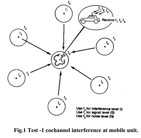
Co channel interference which occurs in one channel will occur equally in all the other channels in a given area. We can then measure co channel interference by selecting any one channel (as one channel represents all the channels) and transmitting on that channel at all co channel sites at night while the mobile receiver is travelling in one of the co channel cells. While performing this test we watch for any change detected by a field-strength recorder in the mobile unit and compare the data with the condition of no co channel sites being transmitted. This test must be repeated as the mobile unit travels in every co channel cell. To facilitate this test, we can install a channel scanning receiver in one car. One channel (f1) records the signal level (no co channel condition), another channel (f2) records the interference level (six-co channel condition is the maximum), while the third channel receives f, which is not in use. Therefore the noise level is recorded only in f3.
We can obtain, in decibels, the carrier to interference ratio C/I by subtracting the result obtained from f2 from the result obtained from f1 (carrier minus interference C - I) and the carrier-to noise ratio C/N by subtracting the result obtained from f3 from the result obtained from f2 (carrier minus noise C — N). Four conditions should be used to compare the results.
1. If the carrier-to-interference ratio C / I is greater than 18 dB throughout most of the cell, the system is properly designed.
2. If C/I is less than 18 dB and C/N is greater than 18 dB in some areas, there is co channel interference
3. If both C/N and C/I are less than 18 dB and C/N =C/I in a given area, there is a coverage problem.
4. If both C/N and C/I are less than 18 dB and C/N> C/I in a given area, there is a coverage problem and co channel interference.
 |
| co channel interference at mobile unit |
Test 2—find the co channel interference area which affects a cell site:
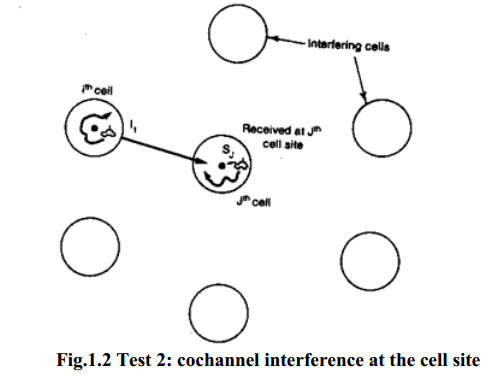
The reciprocity theorem can be applied for the coverage problem but not for co channel interference. Therefore, we cannot assume that the first test result will apply to the second test condition. We must perform the second test as well. Because it is difficult to use seven cars simultaneously, with each car travelling in each co channel cell for this test, an alternative app roach may be to record the signal strength at every co channel cell site while a mobile unit is traveling either in its own cell or in one of the co channel cells shown in Fig. 1.2.
First we find the areas in an interfering cell in which the top 10 percent level of the signal transmitted from the mobile unit in those areas is received at the desired site (Jth cell in Fig. 1.1). This top 10 percent level can be distributed in different areas in a cell. The average value of the top 10 percent level signal strength is used as the interference level from that particular interfering cell. The mobile unit also travels in different interfering cells. Up to six interference levels are obtained from a mobile unit running in six interfering cells. We then calculate the average of the bottom 10 percent level of the signal strength which is transmitted from a mobile unit in the desired cell (Jth cell) and received at the desired cell site as a carrier reception level. Then we can reestablish the carrier-to-interference ratio received at a desired cell, say, the Jth cell site as follows.
The number of cochannel cells in the system can be less than six. We must be aware that all Cj and Ii were read in decibels, Therefore, a translation from decibels to linear is needed before summing all the interfering sources. The test can be carried out repeatedly for any given cell. We then compare
Cj/I and Cj/N
and determine the cochannel interference condition, which will be the same as that in test 1. Nj is the noise level in the Jth cell assuming no interference exists,
 |
| Test 2: cochannel interference at the cell site |

