Explain the designing of the directional antenna under the practical case conditions for K=4, K=7 and K=12 with all suitable values and explaining each of them
4. Explain the designing of the directional antenna under the practical case conditions for K=4, K=7 and K=12 with all suitable values and explaining each of them.
Design of a Directional Antenna System: When the call traffic begins to increase, we need to use the frequency spectrum efficiently and avoid increasing the number of cells K in a seven-cell frequency reuse pattern. When K increases, the number of frequency channels assigned in a cell must become smaller (assuming a total allocated channel divided by K) and the efficiency of applying the frequency reuse scheme decrease.
Instead of increasing the number K in a set of cells, let us keep K =7 and introduce a directional antenna arrangement. The cochannel interference can be reduced by using directional antenna. This means that each cell is divided into three or six sectors and uses three or six directional antennas at a base station. Each sector is assigned a set of frequencies (channels). The interference between two cochannel cells decreases as shown Fig.4.2
Directional antennas in K=7 cell patterns:
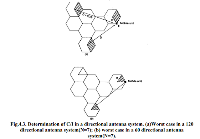
Three sector case: The three-sector case is shown in Fig.4.2. To illustrate the worst case situation, two cochannel cells are shown in Fig. 4.3(a). The mobile unit at position E will experience greater interference in the lower shaded cell sector than in the upper shaded cellsector site. This is because the mobile receiver receives the weakest signal from its own cell but fairly strong interference from the interfering cell.
 |
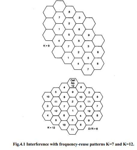
| Interference with frequency-reuse patterns K=7 and K=12 |
In a three-sector case, the interference is effective in only one direction because the front-to-back ratio of a cell-site directional antenna is at least 10 dB or more in a mobile radio environment. The worst-case cochannel interference in the directional-antenna sectors in which interference occurs may be calculated. Because of the use of directional antennas, the number of principal interferers is reduced from six to two (Fig.4.2). The worst case of C/I occurs when the mobile unit is at position E, at which point the distance between the mobile unit and the two interfering antennas is roughly D + (R/2); however, C/I can be calculated more precisely as follows. The value of C/I can be obtained by the following expression (assuming that the worst case is at position E at which the distances from two interferes are D + 0.7R and D).
.PNG) |
| Interfering cells shown in a seven cell system (two-tiers) |
The C/I received by a mobile unit from the 120° directional antenna sector system expressed in Eq. above greatly exceeds 18 dB in a worst case. Equation above shows that using directional antenna sectors can improve the signal-to-interference ratio, that is, reduce the cochannel interference. However, in reality, the C/I could be 6 dB weaker than in Eq. given above in a heavy traffic area as a result of irregular terrain contour and imperfect site locations. The remaining 18.5 dB is still adequate.
Six-sector case: We may also divide a cell into six sectors by using six 60°-beam directional antennas as shown in Fig.4.2. In this case, only one instance of interference can occur in each sector as shown in Fig, 4.2. Therefore, the carrier-to-interference ratio in this case is which shows a further reduction of cochannel interference. If we use the same argument as we did for Eq. above and subtract 6 dB from the result of Eq. the remaining 23 dB is still more than adequate. When heavy traffic occurs, the 60°-sector configuration can be used to reduce cochannel interference. However, fewer channels are generally allowed in a 60° sector and the trunking efficiency decreases. In certain cases, more available channels could be assigned in a 60° sector.
Directional antenna in K = 4 cell pattern:
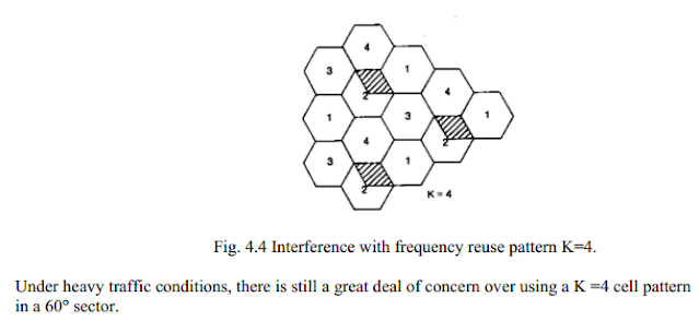
Three-sector case: To obtain the carrier-to-interference ratio, we use the same procedure as in the K = 7 cell-pattern system. The 120° directional antennas used in the sectors reduced the interferers to two as in K = 7 systems, as shown in Fig.4.4. We can apply Eq. here. For K = 4, the value of q = 3.46; therefore, Eq. becomes
 |
| Interference with frequency reuse pattern K=4 |
Comparing K =7 and N =4 systems:
A K =7 cell pattern system is a logical way to begin an omnicell system. The co-channel reuse distance is more or less adequate, according to the designed criterion. When the traffic increases, a three sector system should be implemented, that is, with three 120° directional antennas in place. In certain hot spots, 60° sectors can be used locally to increase the channel utilization.
If a given area is covered by both K=7 and K=4 cell patterns and both patterns have a six-sector configuration, then the K=7 system has a total of 42 sectors, but the K=4 system has a total of only 24 sectors and, of course, the system of K=7 and six sectors has less cochannel interference.
One advantage of 60° sectors with K=4 is that they require fewer cell sites than 120 sectors with K=7. Two disadvantages of 60 deg sectors are that (1) they require more antennas to he mounted on the antenna mast and (2) they often require more frequent handoffs because of the increased chance that the mobile units will travel across the six sectors of the call. Furthermore, assigning the proper frequency channel to the mobile unit in each sector is more difficult unless the antenna height at the cell site is increased so that the mobile unit can be located more precisely. In reality the terrain is not flat, end coverage is never uniformly distributed; in addition, the directional antenna front-to-back power ratio in the field is very difficult to predict. In small cells, interference could become uncontrollable; then the use of a K = 4 pattern with 60 deg sectors in small cells needs to be considered only for special implementations such an portable cellular systems or narrow beam applications. For small cells, a better alternative scheme is to use a K =7 pattern with 120° sectors plus the underlay-overlay configuration.


