CMOS with transmission gates
March 13, 2024
- Discuss in detail the characteristics of CMOS Transmission gates.
- Explain Transmission gates with neat sketches.
- List out limitations of pass transistor logic. Explain any two techniques used to overcome limitations.
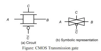
- A transmission gate in conjunction with simple static CMOS logic is called CMOS with transmission gate.
- A transmission gate is parallel pairs of nMOS and pMOS transistor.
- A single nMOS or pMOS pass transistor suffers from a threshold drop.
- Transmission gates solve the threshold drop but require two transistors in parallel.
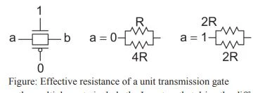
- The resistance of a unit-sized transmission gate can be estimated as R for the purpose of delay estimation.
- Current flow the parallel combination of the nMOS and pMOS transistors. One of the transistors is passing the value well and the other is passing it poorly.
- A logic-1 is passed well through the pMOS but poorly through the nMOS.
- Estimate the effective resistance of a unit transistor passing a value in its poor direction as twice the usual value: 2R for nMOS and 4R for pMOS.
 |
| CMOS Transmission gate |
- The given below figure shows the parallel combination of resistances. When passing a 0, the resistance is R || 4R = (4/5)R.
- The effective resistance passing a 1 is 2R || 2R = R.
- Hence, a transmission gate made from unit transistors is approximately R in either direction.
- Transmission gates are built using equal-sized nMOS and pMOS transistors.
- Boosting the size of the pMOS transistor only slightly improves the effective resistance while significantly increasing the capacitance.
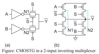
- Figure (a) redraws the multiplexer to include the Inverters that drive the diffusion inputs but to exclude the output inverter. Figure (b) shows this multiplexer drawn at the transistor level.
 |
| Effective resistance of a unit transmission gate |


