Operating regions of MOS transistor
March 04, 2024
Draw the small signal model of device during cut-off, linear and saturation.
Discuss the cutoff, linear and saturation region operation of MOS transistor.
The MOS transistor operates in cutoff region, linear region and saturation region
Cutoff region:
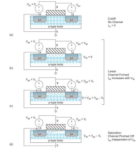
- In Figure 3(a), the gate-to-source voltage (Vgs) is less than the threshold voltage (Vt) and source is grounded.
- Junctions between the body and the source or drain are reverse biased, so no current flows. Thus, the transistor is said to be OFF and this mode of operation is called cutoff.
- If Vgs < Vt , the transistor is cutoff (OFF).
Linear (Active) Region:
- In Figure 3(b), the gate voltage is greater than the threshold voltage.
- An inversion region of electrons, called the channel connects the source and drain, creating a conductive path and making the transistor ON.
- If Vgs > Vt , the transistor turns ON. If Vds is small, the transistor acts as a linear resistor, in which the current flow is proportional to Vds.
- The number of carriers and the conductivity increases, with the gate voltage.
 |
| nMOS transistor demonstrating cutoff, linear, and saturation regions of operation |
- The voltage between drain and source is Vds = Vgs - Vgd. If Vds = 0 (i.e., Vgs = Vgd), there is no electric field to push current from drain to source.
- When a small positive voltage Vds is applied to the drain (Figure 3(c)), current Ids flows through the channel from drain to source.
- This mode of operation is termed as linear, resistive, triode, nonsaturated, or unsaturated. Saturation region:
- The current increases with increase in both the drain voltage and gate voltage.
- If Vds becomes sufficiently large that Vgd < Vt , the channel is no longer inverted near the drain and becomes pinched off (Figure 3(d)).
- As electrons reach the end of the channel, they are injected into the depletion region near the drain and accelerated toward the drain.
- Above this drain voltage, current Ids are controlled only by the gate voltage. This mode is called saturation.
- If Vgs > Vt and Vds is large, the transistor acts as a current source, in which the current flow becomes independent of Vds.
Explain the three different types of modes of operation of pMOS transistor
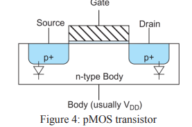
- The pMOS transistor in Figure 4 operates in just the opposite fashion. The n-type body is tied to high potential, junctions of p-type source and drains are normally reverse-biased.
- When the gate has high potential, no current flows between drain and source.
- When the gate voltage is lowered by a threshold Vt, holes are attracted to form a p-type channel beneath the gate, allowing current to flow between drain and source.
 |
| pMOS transistor |
Tags

