IDEAL I-V CHARACTERISTICS OF MOS TRANSISTOR
March 04, 2024
Derive an expression for Ids of nMOS in linear and saturated region. (April 2019-6M)
Derive an expression to show the drain current of MOS for various operating region. Explain one non-ideality for each operating region that changes the drain current. (NOV 2018)
Explain the dynamic behavior of MOSFET transistor with neat diagram. (April 2018)
Explain the electrical properties CMOS. (Nov 2017)
Explain in detail about the ideal I-V characteristics of a NMOS and PMOS device. (MAY 2013)
Discuss in detail with necessary equations the operation of MOSFET and its current-voltage characteristics. (April/May 2011, May 2016).
Derive drain current of MOS device in different operating regions. (Nov/Dec 2014) (May/June 2013) (Nov 2012, Nov 2016)
Explain in detail about the ideal I-V characteristics and non-ideal I-V characteristics of a NMOS and PMOS device. (May/June 2013)
Derive expressions for the drain-to-source current in the non saturated and saturated regions of operation of an nMOS transistor. (Nov 2007, Nov 2008) [April / May – 2023]
MOS transistor has three regions of operation:
1. Cutoff (or) sub threshold region
2. Linear region (or) Non saturation region
3. Saturation region
- The current through an OFF transistor is zero. When a transistor turns ON (Vgs > Vt), the gate
- attract electrons to form a channel.
- Current is measured from the amount of charge in the channel.
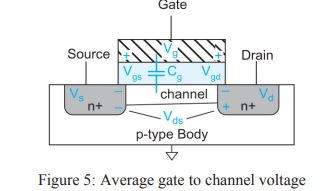
- The charge on each plate of a capacitor is Q = CV. Thus, the charge in the channel Qchannel is
- Qchannel = Cg (Vgc - Vt)
- where Cg : Capacitance of the gate to the channel
- Vgc - Vt : Amount of voltage attracting charge to the channel.
- If the source is at Vs and the drain is at Vd ,
- Average channel voltage is Vc = (Vs + Vd)/2 = Vs + Vds /2.
- Gate and channel voltage Vgc is Vg – Vc = Vgs – Vds /2,
 |
| Average gate to channel voltage |
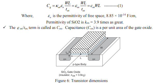
If the gate has length L and width W and the oxide thickness is tox, as shown in Figure 6, Then the capacitance Cg is
 |
| Transistor dimensions |
- Average velocity (v) of carrier is proportional to the lateral electric field (field between source and drain). The constant of proportionality µ is called the mobility.
- v = µE --------------(2)
- The electric field E is the voltage difference between drain and source (Vds) divided by the channel length (L).
- The time required for carriers to cross the channel is L divided by v.
- The current between source and drain is the total amount of charge in the channel divided by the time required to cross.
Tags


