Explain the keeper logic family with neat diagrams
March 13, 2024
Keepers
- Explain the keeper logic family with neat diagrams.
- Briefly discuss the signal integrity issues in dynamic design.
- Dynamic circuits have poor input noise margins.
- If the input rises above Vt,, while the gate is in evaluation, the input transistors will turn ON weakly and can incorrectly discharge the output.
- Both leakage and noise margin problems can be addressed by adding a keeper circuit.
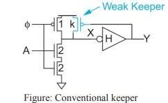
- Figure shows a conventional keeper on a domino buffer. The keeper is a weak transistor that holds, or staticizes, the output at the correct level when it would otherwise float.
- When the dynamic node X is high, the output Y is low and the keeper is ON to prevent X from floating.
- When X falls, the keeper initially opposes the transition, so it must be much weaker than the pulldown network.
- Eventually Y rises, turning the keeper OFF and avoiding static power dissipation.
 |
| Conventional keeper |
- The keeper must be strong enough to compensate for any leakage current drawn when the output is floating and the pulldown stack is OFF.
- Strong keepers also improve the noise margin, because when the inputs are slightly above Vt, the keeper can supply enough current to hold the output high.

