Effective Resistance
March 10, 2024
- Discuss in detail about the resistive and capacitive delay estimation of a CMOS inverter circuit. (or) Briefly explain about the RC delay model.
- RC delay model approximates the nonlinear transistor I-V and C-V characteristics with an average resistance and capacitance over the switching range of the gate.
Effective Resistance:
- The RC delay model treats a transistor as a switch in series with a resistor.
- The effective resistance is the ratio of Vds to Ids.
- A unit nMOS transistor is defined to have effective resistance R.
- An nMOS transistor of k times unit width has resistance R/k, because it delivers k times as much current.
- A unit pMOS transistor has greater resistance, generally in the range of 2R–3R, because of its lower mobility.
- According to the long-channel model, current decreases linearly with channel length (L) and hence resistance is proportional to L.
Gate and Diffusion Capacitance:
- Each transistor has gate and diffusion capacitance.
- C is the gate capacitance of a unit transistor. A transistor of k times unit width has capacitance kC.
- Diffusion capacitance depends on the size of the source/drain region.
- Wider transistors have proportionally greater diffusion capacitance. Increasing channel length, increases gate capacitance proportionally but does not affect diffusion capacitance.
Equivalent RC Circuits:
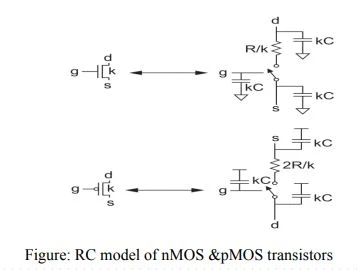
- Figure shows equivalent RC circuit models for nMOS and pMOS transistors of
- width k with contacted diffusion on both source and drain.
- The pMOS transistor has approximately twice the resistance of the nMOS transistor,
- because holes have lower mobility than electrons.
 |
| RC model of nMOS &pMOS transistors |

