
Pass Transistor Logic
March 12, 2024
- Explain Pass transistor logic with neat sketches.
- Explain the pass transistor logic and show how complementary pass transistor logic and double pass transistor logic are applied for 2: 1 multiplexer.
- In pass-transistor circuits, inputs are applied to the source/drain diffusion terminals.
- These circuits build switches using either nMOS pass transistors or parallel pairs of nMOS and pMOS transistors called as transmission gates.
- The nMOS transistors pass ‘0’s well but 1’s poorly. Figure (a) shows an nMOS transistor with the gate and drain tied to VDD.
- Initially at Vs = 0. Vgs > Vtn, so the transistor is ON and current flows.
- Therefore, nMOS transistors attempting to pass a 1 never pull the source above VDD – Vtn. This loss is called a threshold drop.
- The pMOS transistors pass 1’s well but 0’s poorly.
- If the pMOS source drops below |Vtp|, the transistor cuts off.
- Hence, pMOS transistors only pull down to a threshold above GND, as shown in Figure (b).

- Figures show an implementation of the AND function and 2x1 multiplexer using only NMOS transistors.
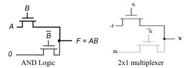
- In AND gate, if the B input is high, the top transistor is turned ON and copies the input A to the output F.
- When B is low, the bottom pass transistor is turned ON and passes a 0.
- In 2x1 multiplexer, if the S selection input is high, the top transistor is turned ON and allows input A to the output Y.
- When S is low, the bottom pass transistor is turned ON and passes the B input.
- An NMOS device is effective at passing a 0 but is poor at pulling a node to VDD. When the pass transistor pulls a node high, the output only charges up to VDD -Vtn.
Application:
Pass transistors are essential to the design of efficient 6-transistor static RAM cells used in modern systems.
Formal Method for P-T Logic Derivation
Complementary function can be implemented from the same circuit structure by applying complementary principle:
Complementary Principle: Using the same circuit topology, with pass signals inverted, complementary logic function is constructed in CPL.
By applying duality principle, a dual function is synthesized:
Duality Principle: Using the same circuit topology, with gate signals inverted, dual logic function is constructed.
Following pairs of basic functions are dual:
- AND-OR (and vice-versa)
- NAND-NOR (and vice-versa)
- XOR and XNOR are self-dual (dual to itself)

Complementary: AND ==> NAND
Duality: AND ==> OR
